The GWinput file
This guide documents the structure of the GWinput file, the primary input file used by the GW package. The GW suite reads some of its input from the GW category of the ctrl file, and other data from GWinput.
GWinput is structured roughly like the ctrl file with categories and tags within categories, but its syntax is a little different and its structure is more primitive. Much of GWinput is not easy to read, or to construct by hand, but you can (and are advised to) create a template GWinput from the ctrl file, using lmfgwd --job=-1 as explained for example, in this tutorial or this one.
Note: This documentation was written for the classic GW implementation (driven by shell script lmgwsc). This documentation continues to be relevant for the modern implementation (driven by shell script lmgw.sh) because it requires similar information — only lmgw.sh may acquire it from a different source. The only GWinput category lmgw.sh requires is the product basis category. lmgw.sh no longer reads the QPNT category or the QFOREPS category; instead information is supplied in the ctrl file or by command line switches as explained in the documentation for these categories.
In the current implementation the most important tags in general category have been subsumed into the ctrl file. To maintain backwards compatibility tags in GWinput’s general category are parsed by GW executables in the modern version. Any tags found there take precedence over corresponding tags in the ctrl file. Correspondences between tags in GWinput and tags in the ctrl file are explained below. Look at the documentation at the start of the general category for tags to particularly watch out for. At some point in the future all of GWinput will be subsumed into the ctrl file.
This documentation denotes Ref. I as a reference to PRB76 165106 (2007).
Table of Contents
- How input is organized
- The general category
- The PRODUCT_BASIS category
- The QPNT category
- The PBASMAX category
- The QforEPS and QforEPSL categories
How input is organized
File GWinput is the main put file for the GW package. Its structure has the tag-value style roughly similar to the ctrl file, but it is much less sophisticated. All but the first category is delimited html-style, e.g.
<PRODUCT_BASIS>
...
</PRODUCT_BASIS>
Categories must be ordered as follows:
(general, no name or delimiter)
<PRODUCT_BASIS>
...
</PRODUCT_BASIS>
<QPNT>
...
</QPNT>
<PBASMAX>
...
</PBASMAX>
<QforEPS>
...
</QforEPS>
Some lines within a category are comments; some require a fixed order though the first (general) category do not. The user is strongly advised to make a GWinput template using lmfgwd --job=-1, and edit it.
<PBASMAX> is optional; <QforEPS> is needed only to compute macroscopic the dielectric function or magnetic susceptibility at specified k points.
The general category
The general category has the structure
tag data
data may be a string, a real number, an integer or a logical, and sometimes a vector of numbers.
Lines beginning with, or text following, a ! are comments, and ignored by the reader.
With the classic implementation, some tags are optional (the entire category is optional with the modern implementation).
Below is a sample general category. The first column was added to label lines; they are described following the box.
Some key tags to watch out for are emax_sigm, QpGcut_psi, and QpGcut_cou, especially the last, as it affects the execution time a great deal. Unfortunately it is not possible to construct a robust default that is efficient as possible while still being accurate. It is a parameter you need to monitor. Similarly dw (and omg_c) affect both time and memory requirements. Default for these two are more robust. The driver lmfgwd assigns conservative default values, and you probably can increase them with little loss in accuracy, as described below.
!Verbose    41  ! 0-->default; 100-->debug
GWversion   12  ! See discussion below
!CoreOrth  off  ! off --> Do not orthogonalize core to valence (default)
!EXonly   .15   ! for exchange-only calculations
!EIBZmode off   ! turn off to suppress use of symmetrization in calculating polarization
!TimeReversal off ! when time-reversal symmetry is broken
KeepEigen  on   ! keep eigenfunctions in memory
KeepPPOVL  on   ! keep PPOVL in memory
n1n2n3  4  4  4 ! for GW BZ mesh
AnyQ off        ! Specify a particular list of k points where to calculate the self-energy
!Chi_RegQbz on  ! Offset Gamma point mesh for chi.  on => no offset
BZmesh     1    ! If 2, offset k mesh for chi so it straddles the Gamma point.
WgtQ0P     0.01 ! Weight for offset Gamma point used when BZmesh is 2
NormChk    0    ! 1,2 writes norm check files (diagonal or full)
!Q0PChoice  2   ! 1s digit sets Q0Pscale.  1(default):sets Q0Pscale=0.1, near q->0 limit   2: Q0Pscale = 1/q^2 average in Gamma region
!               ! 10s digit 1 => make off offset points the same length
!Q0Pscale .1    ! Overrides 1s digit of Q0PChoice, if present.  Set Q0Pscale to given value.
!Q0Plcuto {lmax} ! Zero out L components in w_L for L larger than lmax, Eq. 33, J. Phys. Soc. Japan 83, 094711
!Q0Pmcut (mmax} ! Zero out m components in w_L, for m less than or equal to mmax  Eq. 33, J. Phys. Soc. Japan 83, 094711
!Vkappa 2e-5    ! Artificial screening parameter for Coulomb interaction.  Default value 1e-4
QpGcut_psi 2.7  ! |q+G| cutoff for eigenfunction
QpGcut_cou 2.2  ! |q+G| cutoff for coulomb int.
unit_2pioa off  ! off --> units of 2 preceding Gcut are a.u.; on--> units are 2*pi/alat
alpha_OffG 1    ! (a.u.) parameter (auxiliary function, offset-Gamma method)
!nband_chi0 999 ! nband cutoff for chi0  (Optional)
!emax_chi0 999. ! emax  cutoff for chi0, Ry  (Optional)
!nband_sigm 999 ! nband cutoff for Sigma (Optional)
emax_sigm 2.5   ! Energy cutoff for Sigma, Ry (Optional)
dw       0.01   ! mesh spacing along Real axis (Hartree)
omg_c    0.1    ! mesh spacing increases linearly with w: becomes 2*dw at omg_c
iSigMode 3      ! QSGW mode switch (QSGW only)
niw      6      ! # freq. on Im axis; used for integration to make Sigma_c
delta    -1e-4  ! delta-function broadening for calc. x0, a.u.. delta<0 => tetrahedron
deltaw   0.02   ! width in finite diff for sigma energy derivative, a.u.
esmr     3e-3   ! Broadening in the poles of G(LDA) (hsfp0)
GaussSmear on   ! on  => broadening of poles in G(LDA) by Gaussian
!mixbeta  .25   ! mixing of input, output sigma for self-consistency
!mixpriorit 2
UseBSEW   0     ! include BSE (ladder diagram) contributions to W
NumCondStates 8 ! (BSE only) number of conduction states to include in 2-particle hamiltonian
NumValStates 3  ! (BSE only) number of valence states to include in 2-particle hamiltonian
MinOmega_BSE 0.0! (BSE only) minimum frequency for BSE diectric function for optics
MaxOmega_BSE 2.0! (BSE only) maximum frequency for BSE diectric function for optics
Qvec_bse 1 1 1  ! (BSE optics only) q-vector for single-shot BSE dielectric function
ImagEner1 -0.08 ! (BSE only, Ry, default=0.02) broadening at the minimum frequency for optics
ImagEner2 0.107 ! (BSE only, Ry) broadening at the maximum frequency for optics; it varies linearly between minimum and maximum frequency
x0_small_BSE off! (BSE only) x0_small_BSE on is a special purpose mode; See documentation below
NumValBSE_no 9  ! (BSE only) Used when x0_small_BSE is on. See documentation below
numOmega_BSE 999! (BSE only)
NLF_corr_BSE on ! (BSE only)
Tags by referenced by line:
1 Controls how much information is written to stdout (verbosity).
2 GWversion controls changes in functionality as the GW code has evolved. It consists of a compound of digits.
Note: GWversion applies to the classic code only. In the new code GWversion is always 16.
- 1s digit concerns offset Gamma method.
- Compatible with code as of Sep 2012.
- include local field correction when calculating W(q=0); same as LFC@Gamma, Sep12 version of auxiliary function
- Same as 1, uses auxiliary function dated August 2014.
… The following are recommended. All perform the function of option 4. - Use the bare coulomb calculated at the offset Gamma point itself rather than at q=0.
- Subtract χ000(0,0) from all noninteracting χ0(q,ω). χ000 is the G=G’=0 component of χ0. It should vanish, but does not exactly for numerical reasons. Subtracting it should help to stabilize the offset gamma method.
- Similar to (5), but subtract χ000(0,ω) from all χ0(q,ω).
- Use the (slightly) screened Coulomb interaction 4π/(q2+Vkap) in place of the bare one when estimating average W(q=0) with the offset Gamma method. Not recommended.
- Combination of options 5 and 7.
- Combination of options 6 and 7.
- 10s digit
- number of intermediate states are computed relative to , not ω (this is a bug fix)
- alternative analytic auxiliary functions to regularize singularity at q→0 (q0irre.sc.m.F)
- 100s digit
- alternative estimate for average SE high lying states (hqpe.sc.m.F)
- A special purppose mode that rotate sigm in basis of LDA eigenfunctions (hqpe.sc.m.F)
- Use high accuracy but slow Bessel functions (not usually necessary)
Concerning the 1s digit, offset gamma points are constructed to replace the Coulomb singularity with an average value in the central cell containing the Gamma point. The algorithm normally starts with 6 points, but they may be reduced by point group symmetry. Offset gamma points are generated by qg4gw and stored in file Q0P.
GWversion<14 is not recommended. GWversion 15 appears to be significantly better than GWversion 14, but experience is limited so far (Sep 2020). (The difference in the two should decrease with increasing Q0Pscale, but the error of both increases with Q0Pscale owing to finite-difference errors.) GWversion 15 appears to be signficantly better but experience is limited so far (Sep 2020).
GWversion 16 and GWversion 15 appear to yield almost the same self-energies and dielectric function ε at low ω. As might be expected, ε for GWversion 16 and GWversion 15 begin to diverge when ω becomes large. At least in NiO, GWversion 16 reaches the appropriate large ω limit (Re ε = 1, Im ε = 0), while GWversion 14 and GWversion 15 have difficulty; see figure below for dielectric response in NiO.
Use GWversion 0 for best compatibility with the Sep 2012 version of code.
Click on the image below to see how GWversion affects the QSGW bandgap in CdTe.


The left figure shows the bandgap in CdTe as a function of the number of k divisions (n1n2n3 nk nk nk), for the following scalings of the offset gamma point radius.
- red : Q0Pscale 0.01
- black : Q0Pscale 0.1
- green : Q0Pscale 0.2
- blue : Q0Pscale 0.4
Data is shown GWversion 15 (solid) and for GWversion 14 (dashed) for Q0Pscale 0.1 and Q0Pscale 0.4.
The right figure shows the gap as a function of Q0Pscale, for GWversion 14 (dashed) and for GWversion 15 (solid).
Note the following:
- The GWversion 15 data is very smooth: all four curves extrapolate to nearly the same fixed point when 1/nk→0 (2.095 ± .05 eV).
- The rate at which the gap converges to the 1/nk→0 limit is sensitive to Q0Pscale. In other systems this sensitivity is smaller (Si and NiO for instance).
- Comparing GWversion 14 and GWversion 15, there is scarcely any difference between them when Q0Pscale is 0.4. This is expected : as Q0Pscale increase the two should become more similar.
- For Q0Pscale 0.1 a difference begins to appear for large nk. Errors appear in the GWversion 14 case because the offset point is close enough to gamma so that 1/χ000(0,0) is not negligible compared to 4π/q2.
- In NiO (not shown) GWversion 14 and GWversion 15 are significantly different until Q0Pscale reaches 0.4. For GWversion 15, the gap depends only weakly on Q0Pscale, unless it is set too small (< 0.05).
- The right figure highlights the difference between GWversion 14 and GWversion 15 in another way, plotting the gap for the 6×6×6 k mesh as a function of Q0Pscale. GWversion 15 is stable even for very small Q0Pscale, while GWversion 14 begins to break down for Q0Pscale<0.1.
- GWversion 15 and GWversion 16 generate nearly identical self-energies and dielectric functions at low frequency. The high-frequency part of ε can differ considerably however; see the NiO case below.
Click on the image below to see how GWversion affects the dielectric function in NiO.


The left figure shows real and imaginary parts of the macroscopic dielectric function in NiO (more precisely q=(0,0,0.015)2π/a), for a 4×4×4 k mesh, as a function of frequency ω (eV). Setups taken from the standard test suite (see e.g. checks/gw_v15_nio6_mpik.d)
- black solid : GWversion 14
- blue dashed : GWversion 15
- red dotted : GWversion 16
Note that blue and red overlay on each other, which means for low ω, it is not important whether χ0 is corrected by χ000(0,0) or χ000(0,ω).
The right figure shows the same information, plotted over a wide energy window. For small ω, red and blue overlap; for large ω black and blue are similar. Note GWversion 16 (red) readily reaches the appropriate large ω limit : (Re ε = 1, Im ε = 0), while the other two do not.
The static dielectric function (electronic part) is χ0(q=00,ω=0). The Questaal codes do not have an analytic treatment for χ0(q=0,ω=0), so instead one selects a small but finite q to calculate the macroscopic dielectric function. The contrast between GWversion 14 and GWversion 15 is stark when q is very small. (In the table below, GWversion 16 is not shown, as it is indistinguishable from GWversion 15.)
| qz | GWversion | ε(ω=0), Γ mesh | ε(ω=0), offset mesh | GWversion | ε(ω=0), Γ mesh | ε(ω=0), offset mesh |
|---|---|---|---|---|---|---|
| 0.005 | 14 | 13.74777 | 13.75585 | 15 | 4.253386 | 4.231973 |
| 0.010 | 14 | 6.692466 | 6.686967 | 15 | 4.325542 | 4.312672 |
| 0.015 | 14 | 5.383098 | 5.377693 | 15 | 4.328745 | 4.320106 |
| 0.020 | 14 | 4.921219 | 4.919099 | 15 | 4.327576 | 4.323660 |
| 0.040 | 14 | 4.468702 | 4.466160 | 15 | 4.317125 | 4.314121 |
Comparing offset mesh to Gamma centered mesh gives an estimate of the error from internal k integration.
3 If CoreOrth is on, cores are orthogonalized to valence partial waves and . Enforcing orthogonalization condition is needed to ensure the correct behavior in ε as q→0. However, orthogonalization may excessively deform shallow core orbitals, so usually it is safer not to use this switch. It is useful, however, to check how orthogonalization affects results. If it does, you can alternatively include these shallow cores in the secular matrix using local orbitals, which is very reliable and has no problems with orthogonalization.
ctrl file tag corresponding to CoreOrth: no tag at present.
4 Use EXonly for exchange-only calculations. The value following EXonly tells the code how much Hartree Fock character to admix with LDA. Thus use EXonly 1 for Hartree Fock.
ctrl file tag corresponding to EXonly: no tag at present. (this feature is implemented only in the classic code).
5 EIBZmode: by default, symmetry operations are used in calculating the polarizability. We follow a procedure similar to that of Friedrich et al as described in Phys. Rev. B81, 125102. Use EIBZmode off to suppress use of symmetrization.
ctrl file tag corresponding to EIBZmode: no tag at present (this feature is implemented only in the classic code).
6 TimeReversal: Usually the polarizability assumes time-reversal symmetry. Use TimeReversal off if time-reversal is broken.
ctrl file tag corresponding to TimeReversal: GW_TRSYM.
7,8 KeepEigen and KeepPPOVL: to reduce disk access, eignvectors and the overlap matrix of the product basis are read and retained in memory by default. You can cause the GW code to read them from disk every time one is needed. This conserves memory but increases the (slow) disk access.
ctrl file tag corresponding to KeepEigen and KeepPPOVL: no tag at present. (this feature is implemented only in the classic code).
9 n1n2n3: is the number of k divisions along each reciprocal lattice vectors for numerical integration in the Brillouin zone. (It is the analog of BZ_NKABC in the ctrl file.) Requires 3 integers.
ctrl file tag corresponding to n1n2n3: GW_NKABC.
10 AnyQ (for 1-shot GW only) If AnyQ is on, you can specify any k point in which to evaluate the self-energy. Note however that eigenfunctions must be prepared for an entire k mesh for any point you specify not on the regular mesh, so if you specify many such points the calculation can run slowly. AnyQ was used to make Figure 6 in Phys. Rev. B 74, 245125 (2006).
ctrl file tag corresponding to AnyQ: no tag at present (the one-shot code is implemented so far only in the classic code).
11 BZmesh: use this switch to stagger the k mesh in calculating the dielectric function (see Eq. 53 in PRB 76,165105) It should be on (the default) or off. off offsets the mesh to avoid the point, analogous to what BZ_BZJOB does for lmf and related codes; see ctrl file input (but note that BZJOB can accept up to three switches, Chi_RegQbz only one).
ctrl file tag corresponding to BZmesh: no tag at present (this feature is implemented so far only in the classic code).
At times the static limit of macroscopic dielectric function εM(ω→0) can converge very slowly with the number of k divisions nk, so that getting the converged result can be painful. It may happen (and often does) that εM(ω→0) converges with nk from below with the staggered mesh and from above with the usual one. In such a case the two meshes bound εM(0) for finite nk, and should converge in the 1/nk→0 limit. By plotting εM(0) as a function of 1/nk for both meshes at several values of nk, you can extrapolate each of them to 1/nk→0. If the two meshes extrapolate to the same point, it can be taken as a reliable value for εM .
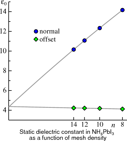 )
)An instance of this is NH4PbI3. The Figure shows εM(0) plotted for the two meshes. Even while εM(0) is not well converged for either mesh (especially the regular one), extrapolating to 1/nk=0 gives much confidence in the converged result.
See also the Brillouin integration page.
12 Chi_RegQbz is the analog of Chi_RegQbz off when calculating the self-energy. It offers the option to staggers the k-mesh in the polarizability when integrating G*W over k.
ctrl file tag corresponding to BZmesh: no tag at present (this feature is implemented so far only in the classic code).
This switch is somewhat analogous to BZ_BZJOB in the ctrl file, though it applies to the internal integration over k to obtain the self energy at some q. For now the latter mesh is always is centered at the Gamma point.
BZMESH should be 1 (the default) or 2. 1 includes the Gamma point (see Eq. 47 in PRB 76,165105).
2 offsets the mesh to avoid the point (see Eq. 53 in PRB 76,165105). 2 is useful for anisotropic Brillouin zones.
Note that for BZMESH 1, the “offset Gamma method” described in PRB 76,165105. has been superseded by similar, but more general approach ; see JPSJ83,094711. BZMESH 2 implies a different treatment for the offset gamma method; the original scheme described in PRB 76,165105 is still used.
Warning (Sep 2020) BZMESH 2 is being revived, but the revision is not yet complete.
13 WgtQ0P is the total weight for the offset gamma method when BZmesh 2 (and is effective only for that case). More precisely it is fraction of the weight taken from regular mesh points near Gamma, and added to a special offset point. In principle, the final result should not depend on WgtQ0p. It is usually OK to take 0.01 (default), but there is a little dependence and you can take smaller values. When WgtQ0p is very small, e.g. 10−5, the QP levels become sensitive to the errors in normalization of the eigenfunction. You can improve the normalization with a larger QpGcut_psi. Normalization is printed out in normchk.dia.
14 NormChk Set to 1 or 2 causes the code to write norm check files (diagonal or full).
ctrl file tag corresponding to BZmesh: no tag at present (this feature is implemented so far only in the classic code).
15 Q0PChoice is a compound of digits.
ctrl file tag corresponding to Q0PChoice: none. For the new GW code, it is recommended that you use GW_Q0PSCALE, and do not use the --offg switch.
- 1s digit can modify the default radius for the offset Gamma points, if Q0Pscale is missing. Q0PChoice 1 sets a relatively small default equivalent to Q0Pscale 0.1; Q0PChoice 2 sets a larger default, equivalent to Q0Pscale 1/√3.
- 10s digit tells the offset gamma point maker to make all offset-gamma points the same radius.
You can also control which points are used to select the final set of offset Gamma points. The full set is reduced by the available symmetry operations. You can pass the following choices through switch --offg= in the lmgw script.
- ktn6 traditional default, equivalent to +qa +qm
- +qa: three points on the positive axes of reciprocal lattice vectors qlat
- −qa: three points on the negative axes of qlat
- +qm: three points on the positive mid plane axes of qlat (or perpendicular if angles < pi/2)
- −qm: three points on the negative mid plane axes of qlat (or perpendicular if angles %lt; pi/2)
17 Q0Pscale sets the radius for the offset Gamma points. Default is 0.1, close to the q→0 limit. See Sec. II-E-2 in PRB 76,165105 for a discussion of the original offset-Gamma method, and JPSJ83,094711 for a discussion of the updated method now implemented in the code.
ctrl file tag corresponding to Q0Pscale: GW_Q0PSCALE.
18 Q0Plcuto It has been found empirically that the higher L components in Eq. 33, of the J. Phys. Soc. Japan 83, 094711 can be sometimes unstable. This tag zeros out wL for L>lmax to improve stability.
ctrl file tag corresponding to n1n2n3: none.
19 Q0Pmcut is similar to Q0Plcut. In 2D systems modelled by periodic slabs with a large vacuum, the m=0 component makes little sense. This tag zeros out m≤mmax0 components of wL, except for the l=0 component.
ctrl file tag corresponding to Q0Plcuto: none.
20 Vkappa: The bare coulomb interaction is replaced by a screened one, . In principle Vkappa should be 0, but results can be unstable when it is too small. Note that Vkappa should always be positive.
ctrl file tag corresponding to Vkappa: GW_VTF.
21 QpGcut_psi is the G cutoff (actually q+G cutoff) in the plane wave expansion of the eigenfunctions.
ctrl file tag corresponding to QpGcut_psi: GW_GCUTB.
22 QpGcut_cou is the G cutoff (actually q+G cutoff) in the plane wave expansion of two particle objects such as and .
ctrl file tag corresponding to QpGcut_cou: GW_GCUTX.
23 unit_2pioa specifies whether QpGcut_psi and are in QpGcut_cou and are in atomic units (off), or in units of 2π/a (on).
ctrl file tag corresponding to unit_2pioa: none.
24 alpha_OffG corresponds to in Eq. 48 in PRB76 165106 (2007). alpha_offG 1d0 corresponds to offset points close to zero, and is usually a good choice. You can check convergence in n1n2n3, varying this number.
ctrl file tag corresponding to alpha_OffG: GW_QOFFP.
25 nband_chi0 limits the number of bands used in computing ε(ω).
ctrl file tag corresponding to nband_chi0: GW_NBAND.
26 emax_chi0: similar to nband_chi0, but limits the bands in computing ε by energy cutoff instead of number of bands.
ctrl file tag corresponding to emax_chi0: GW_ECUTS.
27 nband_sigm limits the number of bands used in computing Σ(ω).
ctrl file tag corresponding to nband_sigm: GW_NBAND.
28 emax_sigm: similar to nband_chi0, but limits the bands in computing ε by energy cutoff instead of number of bands.
ctrl file tag corresponding to emax_sigm: GW_ECUTS.
29,30 dw and omg_c fix the frequency mesh for real-axis integration of the polarizability, Eq. 32 of Ref. I, in atomic Hartree units. For small the mesh points are linearly spaced, separated by dw. If omg_c is not present, mesh points are linearly spaced on the entire grid. Otherwise the spacing gradually increases with , becoming twice dw at . Points on the mesh are interpolated to determine . Point is given by
is approximately dw/2.
Note: the default dw supplied by Questaal assumes a conversative value (0.01 Ha). Most of the time you can safely increase dw, e.g. to 0.04 Ha, with minimal loss in accuracy, which will conserve both memory and time. However, when generating the macroscopic dielectric function, typically you want to make dw much smaller, say 0.001 Ha.
ctrl file tag corresponding to dw and omg_c: GW_DELRE(1:2). Note that GW_DELRE is in atomic Ry units; multiply by 2 to make it equivalent to dw and omg_c.
31 iSigMode Defines kind of quasiparticle self-consistency (how static Σ is extracted from the dynamical one).
iSigMode=3: Use (Eq. 10, mode-A in Ref. I).
iSigMode=1: Use (Eq. 11, mode-B in Ref. I).
iSigMode=5: Use (Eigenvalue-only self-consistency).
There is no “right” choice but 3 has the best formal justification.
ctrl file tag corresponding to iSigMode: GW_MKSIG.
32 niw Number of integration points along the imaginary axis to get , as described in II-F in Ref.I. The integration points are , where is the set of points for a Legendre quadrature in the interval [0,1]. (There is also special treatment of the sharply peaked contribution near .) Convergence is rapid in niw. Tests show niw=6 is sufficient to reach 0.01 eV accuracy in QP levels in Si.
ctrl file tag corresponding to niw: GW_NIME.
33 delta Small imaginary part in Eq. 32 of Ref. I, in atomic Hartree units. turns on tetrahedron integration. Not used at present since the present code only uses Faleev’s fast integration, and tetrahedron integration. delta should be negative.
ctrl file tag corresponding to delta: GW_DELTA.
34 deltaw When is required, e.g. for the Z factor, it is computed numerically with a finite difference. deltaw is the energy spread used in the finite difference.
ctrl file tag corresponding to deltaw: GW_DELTAW.
35,36 esmr Broadening of the poles in the self-energy makers hsfp0 and hsfp0_sc. Poles of the Green function are smeared out by a width esmr. If GaussSmear is on, the smearing has the shape of a Gaussian function; otherwise a rectangular smearing is used. For insulators the value should be smaller than the bandgap (you can use small numbers like 0.001 or even smaller). For metals, the number should be a little larger. Some experimenting is needed, as it depends on the case. For Fe, esmr=1e-2 seems to be a good value.
ctrl file tag corresponding to esmr: GW_GSMEAR.
37,38 mixbeta, mixpriorit In the self-consistency cycle, self-energies are mixed with prior iterations to stabilize convergence. Provided a file sigm is available on disk (taken to be , i.e. the input ), hqpe_sc assembles results from the self-energy maker hsfp0_sc to make a new , and writes to sigm a new estimate for . It takes the linear combination
If mixpriorit is nonzero, hqpe_sc looks for pairs from prior iterations in file mixsigma. If they are available, Anderson mixing is used to estimate a new from a linear combination of and pairs from mixpriorit prior iterations (or as many as available, if fewer than mixpriorit). If mixpriorit is zero, is written. Anderson mixing used is the same as lmf uses to mix input and output charge densities, and some description can be found here. Note in particular the discussion of parameters tj found the lmsig output, file lsg (hqpe_sc in the clssic code, file lqpe).
ctrl file tag corresponding to mixbeta: GW_MIXBETA.
39-50 These are switches connected with the BSE solver that adds ladder diagrams to the polarizability. To add this correction, set UseBSEW to a nonzero value. You also need NumCondStates and NumValStates. Ladders are calculated after W is calculated in the RPA. They can be added in two contexts: when calculating the optics, i.e. the macroscopic dielectric function, and to modify the screened coulomb interaction W, when computing the self-energy Σ.
For optics, ε(ω) is computed in the window MinOmega_BSE < ω < MaxOmega_BSE, for q→0 along the vector given by Qvec_bse. The spectrum is broadened by a broadening which increases linearly in ω from the initial value ImagEner1 at MinOmega_BSE, to a final broadening at ImagEner2.
x0_small_BSE on turns on a special purpose mode that calculating ε, it subtracts the contribution to χ0 from the subset of transitions from the full χ0, and then adds on the BSE contribution. NumValBSE_no tells the BSE solver how many valence states not to include when calculating W.
Equivalents in the ctrl file
- UseBSEW: no equivalent; Make BSE W through a command line switch in lmgw.sh
- NumCondStates → GW_BSE_NC
- NumValStates → GW_BSE_NV
- MinOmega_BSE → GW_BSE_EIMW, first argument
- MaxOmega_BSE → GW_BSE_EIMW, second argument
- ImagEner1 → GW_BSE_IMW, first argument
- ImagEner2 → GW_BSE_IMW, second argument
- Qvec_bse → GW_BSE_QVECS
The PRODUCT_BASIS category
An instance of this category, taken from NiO, is shown below. (The first column was added to label lines; they are described following the box.) NiO has two Ni atoms and two O atoms. Thus the information for sites 1 and 2 should be identical, as and also for sites 3 and 4.
Note: when generating a template for GWinput, lmfgwd automatically generates equivalent product basis information for equivalent sites. Whenever you edit GWinput by hand it is a good idea to check for consistency. lmfgwd can perform a number of checks for you, including checking equivalency of equivalent sites. To run a check, do lmfgwd --job=-2.
<PRODUCT_BASIS>   ! Product basis block
  tolerance = minimum eigenvalue in PB overlap to reduce linear dependency
  3e-4 3e-4 1e-3
  lcutmx(atom) = l-cutoff for the product basis
  4  4  3  3
  atom   l  nnvv  nnc ! nnvv: num. radial functions (valence) for augmentation-waves. nnc = num. for core.
    1    0    2    3
    1    1    3    1
    1    2    3    0
    1    3    2    0
    1    4    2    0
    ...
    3    0    2    1
    3    1    2    0
    3    2    2    0
    3    3    2    0
    3    4    2    0
    ...
  atom   l    n  occ  unocc  :Valence(1=yes, 0=no)
    1    0    1    1    1   ! 4S_p *
    1    0    2    0    0   ! 4S_d
    1    1    1    1    1   ! 4P_p
    1    1    2    1    1   ! 4P_d
    1    1    3    1    1   ! 3P_l
    1    2    1    1    1   ! 3D_p
    1    2    2    0    1   ! 3D_d
    1    2    3    0    1   ! 4D_l
    1    3    1    0    1   ! 4F_p
    1    3    2    0    0   ! 4F_d
    1    4    1    0    0   ! 5g_p
    1    4    2    0    0   ! 5g_d
    ...
    3    0    1    1    1   ! 2S_p *
    3    0    2    0    0   ! 2S_d
    3    1    1    1    1   ! 2P_p
    3    1    2    0    0   ! 2P_d
    3    2    1    1    1   ! 3D_p
    3    2    2    0    0   ! 3D_d
    3    3    1    0    1   ! 4F_p
    3    3    2    0    0   ! 4F_d
    3    4    1    0    0   ! 5g_p
    3    4    2    0    0   ! 5g_d
    ...
  atom   l    n  occ unocc   ForX0 ForSxc :CoreState(1=yes, 0=no)
    1    0    1    0    0      0    0    ! 1S *
    1    0    2    0    0      0    0    ! 2S
    1    0    3    1    0      1    1    ! 3S
    1    1    1    0    0      0    0    ! 2P
    ...
    3    0    1    0    0      0    0    ! 1S *
    ...
2 This line is used as a marker to identify the next line (keyword is tolerance), so it should be present.
3 A list of floating-point numbers. The size of list should range between 1 and 2×lmax+1 numbers, where lmax is the largest integer in line 5. The code will populate any numbers omitted with the last number you supply.
These numbers refer to tolerances in the overlap matrix of product basis functions. Product basis functions of different l are automatically orthogonal, so each l can be treated independently of the others. The overlap matrix constructed from product basis for a particular site and l is diagonalized to form an orthonormal set. Orthogonalized functions with small eigenvalues add little to the hilbert space of functions. Those with eigenvalues below tolerance are discarded, both reducing the size of the basis and avoiding numerical issues stemming from linear dependencies.
For small l it is safer to use small tolerances; but for higher l tolerances can be coarser for the same accuracy. Computational time is more sensitive to the higher l tolerances because they have more functions of different m per radial function.
4 This line is used as a marker to identify the next line (keyword is lcutmx(atom)), so it should be present.
5 specifies the l cutoff lmax for each site. Product functions are expanded to l = 2×lmax. You must supply one lmax for each site. lmax=3 is usually good enough for light sp elements, lmax=4 for transition metals. But as the nucleus becomes heavier and larger, lmax needs to be made somewhat larger. We have not tested the convergence for f shell elements, but lmax=6 is almost certainly safe. Smaller lmax reduces the computational cost, at the expense of accuracy.
By choosing rough tolerances considerable savings in time may be realized for systems with few atoms. But for larger systems, e.g. with 8 atoms or more, the time is limited by the plane wave part of the mixed basis, and there is little advantage to playing with this tolerance. The values autogenerated by lmfgwd –job=-1 are usually pretty safe.
6 This line is used as a marker to identify the next section (keyword is atom), so it should be present.
7-18 This table specifies the number of partial waves in the valence nnvv, and number of core levels nnc, one line for every site and l. nnvv will customarily be two for partial waves and , or three for channels that also have a local orbital . For the first (Ni) atom, there are three s core levels, but only a core because the is included in the valence as a local orbital (note nnvv=3 for the p). O (site 3 or 4) has only one core level, the .
This table is made automatically by lmfgwd –job=-1, and it is tied to the basis. If you change the basis, be sure to check that the table is still valid (lmfgwd –job=-2) or regenerate the table.
19 This line is used as a marker to identify the next section (product basis for valence states, keyword atom), so it should be present.
12-18 This table specifies which partial waves should be used to construct the product basis. There is one line for every l, valence partial wave, and every site. The lines in this table must synchronize with the preceding one. Recall that two partial waves combine to make a single product basis function. From the table in this section, two lists of functions are assembled: one for the first function which enters into the bra (|…>) part of the matrix element and another for the second which enters into the ket (<…|) part of the matrix element.
Column l refers to l quantum number of the partial wave
Column n refers to the type of partial wave (1 for , 2 for , 3 for ).
Column occ if nonzero, is added to the “bra” list
Column unocc if nonzero, is added to the “ket” list.
The remainder of the line is not used, but the template maker supplies a label so you can readily identify the kind of orbital it is. _p refers to principal wave (), _d refers to energy derivative () _l refers to local orbital ().
We have found that including the adds little to the effectiveness of product basis, so the template maker leaves them out. You can always include them by putting 1 in the occ and/or unocc columns.
In the sample section above, the default was altered. For Ni partial waves entering into the “bra” set is : , and the “ket” list is .
This basis is likely larger than needed, e.g. the inclusion of orbitals, and in the unocc column are probably not necessary.
44 This line is used as a marker to identify the next section (product basis for core states, keyword atom), so it should be present.
45-51 This section is the analog for core states of the preceding table. Columns l, n, occ, unocc serve the same function as for the preceding section. Column ForX0 tells the GW code to include this state in the calculation of the polarizability. There is an orthogonalization issue, however, see line 4 in the general section for a discussion.
Column ForSxc tells the GW code to include this state in the calculation of the self-energy.
Return to Table of Contents
The QPNT category
This category is designed for one-shot GW, to select which k points and QP levels for which to make the self-energy.
Hazard: if your system is metallic there are restrictions: you must calculate the self-energy for all k points and occupied states, in order to obtain the Fermi level.
Note: This feature is not used in the current GW code, as at present only the classic code has a 1-shot GW implementation.
A typical instance of this category is shown below. (The first column was added to label lines; they are described following the box.)
<QPNT>  ! Specify particular k-points and bands (one-shot mode)
 --- Specify qp and band indices at which to evaluate Sigma

*** Sigma at all q -->1; to specify q -->0.  Second arg : up only -->1, otherwise 0
  0  0
*** no. states and list of band indices to make Sigma and QP energies
  4
  4 5 6 7
*** q-points (must belong to mesh of points in BZ).
    3
    1     0.0000000000000000     0.0000000000000000     0.0000000000000000
    3    -0.5000000000000000     0.5000000000000000     0.5000000000000000
    7     0.0000000000000000     0.0000000000000000     1.0000000000000000
    ...
</QPNT>
The category as written above applies to 1-shot GW or QSGW calculations. (Extra information must be given when generating the dynamical self-energy; this will be described shortly.)
Lines preceding ‘***’ or ‘###’ are not used (only line 2 in this case). Lines beginning with one of these are markers that flag the start of a subsection following the line.
3-4. This is the marker for the first subsection and its contents. The two integers on line 4 should be 0 or 1. If the first is 1, QP levels are calculated for all q in the irreducible BZ. If it is zero, QP levels are computed only for a list following the third instance of *** (lines 8-13 in this case). For a metal, you should always pick 1 so the Fermi level can be found.
The second integer is usually 0. Choosing 1 causes the code to calculate QP levels for the first spin only. (Useful for an antiferromagnetic system such as NiO).
5-7. This is the marker for the second subsection and its contents. Its purpose is to select particular QP levels which calculate. (You can of course calculate them all but it is faster to make only a subset.) Line 6 tells the reader how many levels to calculate; line 7 lists the levels. It is an error for the list in line 7 to be smaller than number of levels you select.
8-13. This is the marker for the third subsection and its contents. Its purpose is to select the q points. (If the first integer in line 4 is 1, this subsection is not used.) Line 9 tells the reader how many points q you want QP levels for; call this nq. Then follow nq lines specifying the q points.
- The first number is not used
- Each k point must be a point on the mesh you specify; see n1n2n3, line 14 of the general category. The template maker generates a list of all the irreducible points (it was 8 points in this case). You can use a text editor to shuffle the rows (as was done here, to select the Γ, L and X points of a cubic material).
Extra input for the dynamical self-energy
Note: This documentation applies only to the classic code. In the modern implementation, you supply these parameters to command line switches to lmgw.sh.
hsfp0 –job=4 is a special mode that makes the dynamical self-energy. In this mode the reader parses lines in the QPNTS category until one is found begining with ‘****’ (the line must be present). Two numbers must appear in the next line. The two lines should be inserted before the normal part of this category described above.
An example is:
***** ---Specify the q and band indices for which we evaluate the omega dependence of self-energy ---
   0.01 2   (Ry) ! dwplot omegamaxin(optional)  : dwplot is mesh for plotting.
0.01 and 2 are the energy spacing and range over which is calculated. In this mode the usual dw and omg_c (lines 23 and 24 in the general section). The entire range is twice the second number: it extends both above and below the Fermi level.
The PBASMAX category
Not documented.
The QforEPS and QforEPSL categories
These categories apply to modes to calculate dielectric or magnetic response functions. Use one or the other.
Note: This documentation applies only to the classic code. In the modern implementation, you supply k in the GW category of the ctrl file, with tag GW_EPSQ.
Response functions are calculated at selected k points. If you add a line
QforEPSIBZ on
then the list becomes all the q in the irreducible BZ.
Otherwise, use a QforEPS or QforEPSL category. In the former, you specify a list of q points, e.g.
<QforEPS>
0d0 0d0 0.01d0
0d0 0d0 0.02d0
0d0 0d0 0.04d0
</QforEPS>
Alternatively specify q points along symmetry lines (useful for plotting a response function along particular symmetry lines). For example, for a cubic system, the following yields seven q points from X to Γ and another seven from Γ to L (the left end point is omitted).
<QforEPSL>
1d0   0d0  0d0  0d0  0d0 0d0   8
0d0 0d0 0d0    .5d0 .5d0 .5d0  8
</QforEPSL>